Melody Hsu
Last updated Sep 2025
Note: The full Grasshopper code for all the following sections can be downloaded here.
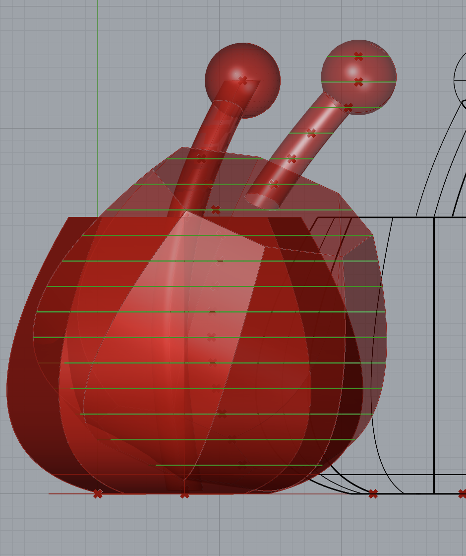
Task 1: Parametric Generation
For this task, we have a form that is parametrized by the following customizable parameters:
- $x,y,z$ coordinates of the form’s location
- Number of segments for base polygon
- Number of segments for middle polygon
- Number of segments for top polygon
- Height of middle polygon (center curve)
- Height of top polygon
- Radii for all three polygons
- $x,y,z$ coordinates of the decorative top sphere
- Radius for decorative top sphere
- $x,y,z$ coordinates of the control point for the curve through center of the form
- Degree of bend of curve
- Radius of extruded cylinder along curve
Below are five variations of the form.


Task 2: 3D-to-2D Slicer
Below is the code snippet that generates the slicing planes that generate the 2D slices that intersect a 3D object.
import rhinoscriptsyntax as rs
import math

def make_layers(spacing,x,y,x_0,y_0,z_0,z_end,axis,custom_vec=None):
    rects = []
    num_layers = int((z_end-z_0)//spacing) + 1

    z_offset = 0
    x_offset = 0.5*x
    y_offset = 0.5*y
    print(custom_vec)
    deg = 0

    for i in range(num_layers + 1):
        p = rs.WorldXYPlane()
        p = rs.MovePlane(p,(x_0-x_offset,y_0-y_offset,z_0+i*spacing-z_offset))
        # code for custom plane angling is omitted here
        # [...]
        rect = rs.AddRectangle(p,2*x,2*y)
        rects.append(rect)
    return rects, num_layers+10

a,nl = make_layers(spacing,x,y,x_0,y_0,z_0,z_end,axis,custom_vec)
The python script computes the number of layers based on the height of the bounding box, given by $z_{end}-z_0$, which are the deconstructed endpoints of the z-axis component of the bounding box. The spacing, i.e. the material thickness, is taken in as a user-defined parameter via slider.
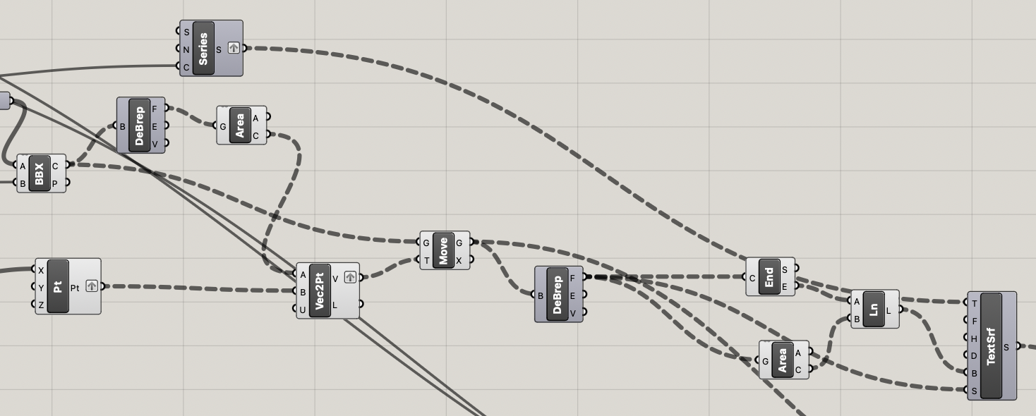
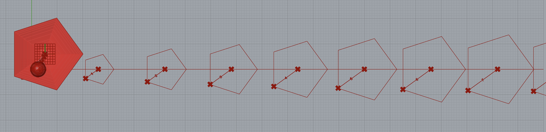
Then, the next step is to get the curves for laser-cutting.
To do this, we use BBX to intersect the planes generated by the Python script and the parametric form.
Then, we map these curves onto distinct locations on the XY plane.
Finally, to print text onto the curves, we compute text baselines using the centroids and endpoints of each laser-cut curve, and then use TexttoSrf to place text on these lines.
A portion of the output is shown below.
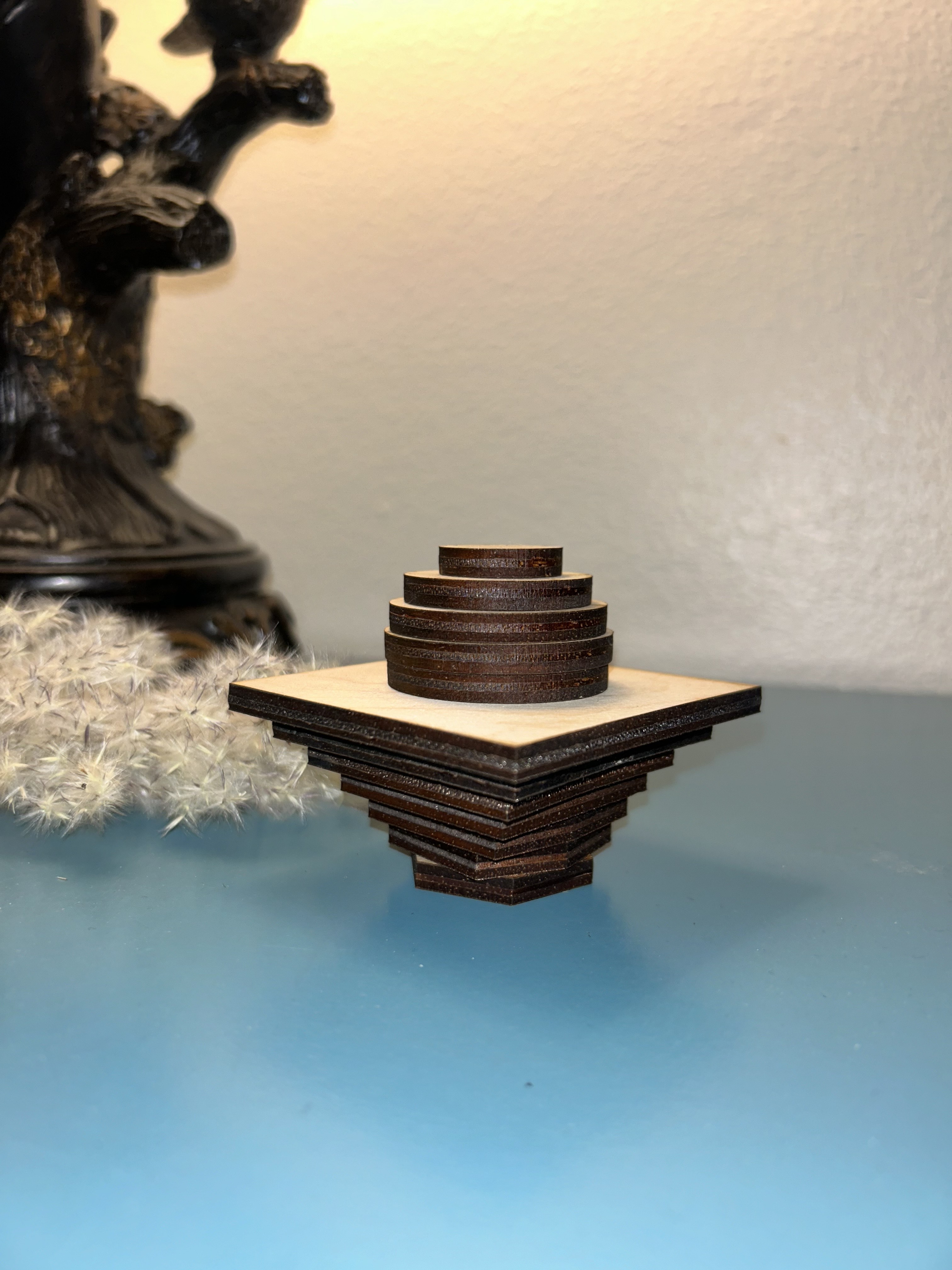
Task 3: Fabrication
Below are two examples of fabricated designs.


Extra Credit: Part 1
Slicing along a custom plane can be accomplished in one of two ways.
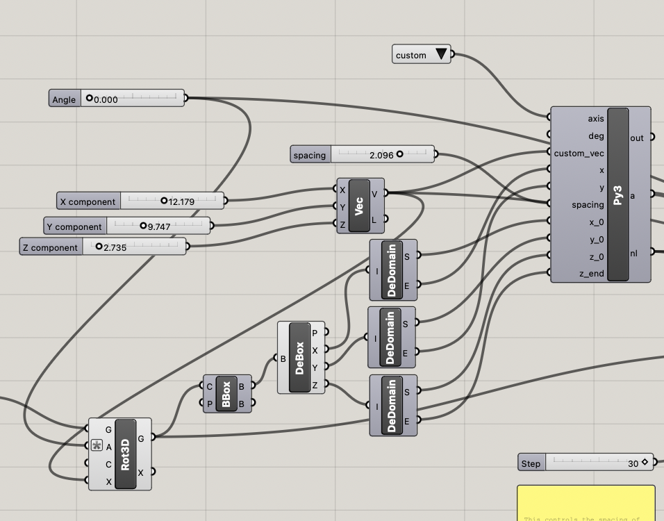
The first approach is to modify the Python script from Task 2 to take in a user-defined axis and a degree of rotation to angle the planes.
The user inputs deg via slider, and then selects which axis they would like to rotate on through a value selector that allows the user to select to slice along the X axis, the Y axis, the Z axis, or a completely “custom” axis defined by a vector input where the $x,y$, and $z$ coordinates are all provided via slider as well.
Below is the code which accomplishes this:
for i in range(num_layers + 1):
        p = rs.WorldXYPlane()
        if axis == "X":
            p = rs.RotatePlane(p,deg,p.XAxis)
            offset = x*math.tan(math.radians(deg))
        if axis == "Y":
            p = rs.RotatePlane(p,deg,p.YAxis)
            offset = -1*x*math.tan(math.radians(deg))
        if axis == "Z":
            p = rs.RotatePlane(p,deg,p.ZAxis)
        if axis == "custom":
            p = rs.RotatePlane(p,deg,custom_vec)
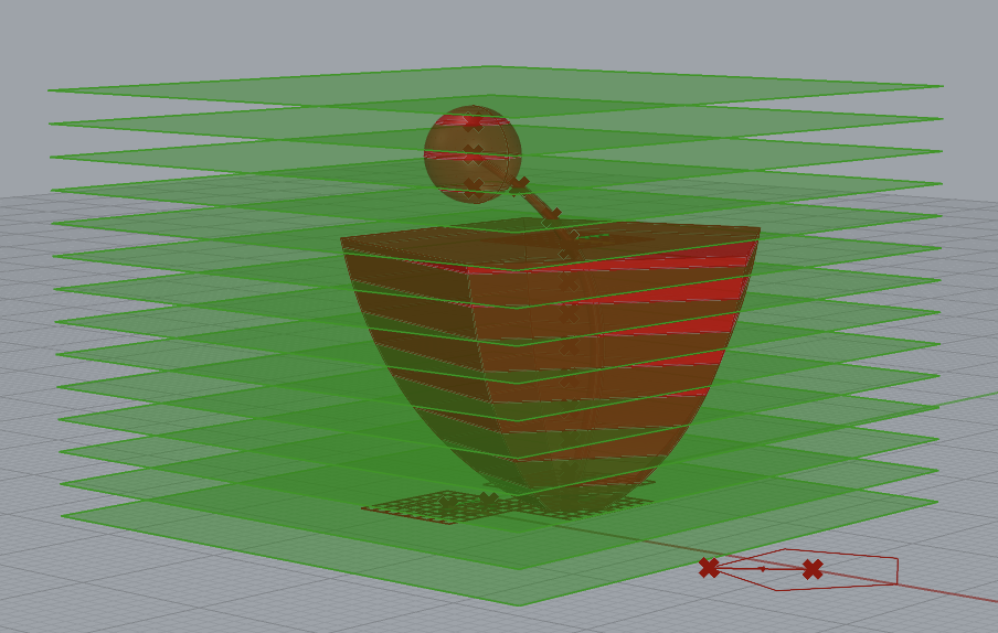
The second approach is to angle the form itself, and then slice the planes through the rotated form.
This accomplishes effectively the same thing, and is easier to manage in that the planes themselves do not have to be rotated when they are moved to the XY-plane for laser cutting.
Below is an image of the result of BBX when applied to the rotated object:
Finally, below is a fabricated object made with the diagonal slicer. Unfortunately, this object does not look much like the actual form that generated it due to an error with the material thickness - probably the material needed to be much thicker, and much lighter than acrylic, to be able to stand on the proper axis.
